Introduction
A single missed step in a stepper motor can throw off an entire 3D print, derail a CNC toolpath, or ruin robotic precision. Yet behind every cleanly executed move is a deceptively simple device — the bipolar stepper motor — converting electrical pulses into exact mechanical motion without needing sensors or feedback.
Ever wondered how these motors know exactly how far to turn and when to stop — all without “knowing” their own position?
Bipolar stepper motors are a key building block in motion control systems, prized for their balance of torque, accuracy, and simplicity. Unlike unipolar designs, bipolar steppers drive both directions of current through each coil, enabling more magnetic force and tighter control in the same physical footprint.
In this article, you’ll learn exactly how bipolar stepper motors work — from their internal components and magnetic principles to how they move, how they’re driven, and where their strengths and trade-offs lie. Whether you’re building a 3D printer, automating a lab tool, or just trying to choose the right motor for a precision task, this guide offers the knowledge you need to make smarter, more confident decisions.
What Is a Bipolar Stepper Motor and Why Is It Used?
Stepper motors are well-known for their ability to produce precise, repeatable motion without the need for encoders or feedback systems. As discussed in the introduction, bipolar stepper motors stand out for their efficiency and torque characteristics, making them a popular choice in precision-driven systems. To understand their role and advantages, we first need to break down what defines them, how they differ from similar designs, and where they fit in modern applications.
Defining Stepper Motors by Structure and Function
At the core, a stepper motor is a brushless, synchronous motor that moves in discrete steps — typically 1.8° per step for standard models (200 steps per revolution). This movement is achieved by energizing electromagnetic windings in a specific sequence, causing the rotor to align with the resulting magnetic field.
A bipolar stepper motor uses two coil windings, and each winding is actively driven in both directions by reversing the polarity of the current. This distinguishes it from unipolar types, which use center-tapped windings and only switch current in one direction per coil half.
The physical structure includes:
- A stator with toothed electromagnets arranged in phases (usually two),
- A rotor with permanent magnets or soft iron teeth,
- And a controller or driver that determines the step sequence.
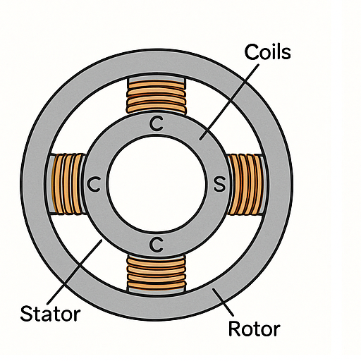
Original diagram generated to illustrate electromagnetic interaction in standard NEMA-class bipolar stepper motors (created July 2025).
When controlled properly, this setup allows for open-loop position control with high repeatability — no encoder required.
What sets bipolar motors apart is their full utilization of the coil windings. Since current can be reversed, both windings participate fully in torque generation, which improves performance in a given physical size.
Bipolar vs. Unipolar: What’s the Real Difference?
While both unipolar and bipolar stepper motors operate on the principle of magnetic field alignment, they differ significantly in how they generate those fields and how efficiently they use their windings.
| Feature | Bipolar Stepper Motor | Unipolar Stepper Motor |
|---|---|---|
| Winding Type | Two coils, no center tap | Two coils with center taps |
| Current Direction | Reversible (bidirectional current) | One-way (uses only half of each coil) |
| Torque Output | Higher for the same motor size | Lower, due to half-coil operation |
| Driver Complexity | Requires H-bridge driver for polarity swap | Simpler driver circuitry |
| Efficiency | More efficient use of copper windings | Less efficient — unused winding segments |
| Wiring | 4 wires | 5 or 6 wires |
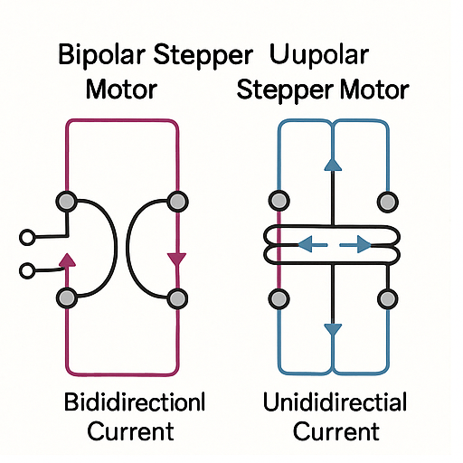
Original technical sketch created to visualize the winding topology and magnetic efficiency differences (July 2025).
The practical implication is that bipolar motors deliver more torque and smoother motion at the cost of slightly more complex electronics. This trade-off is usually acceptable in applications where performance matters more than minimal circuit design.
Notably, modern stepper motor drivers (like the A4988 or TMC2209) simplify this complexity by handling current direction automatically, making bipolar motors more accessible even to hobbyists.
Common Use Cases in Precision Systems
Because of their high torque density, efficient winding use, and smooth microstepping performance, bipolar stepper motors are widely used in systems where repeatable linear or rotary motion is critical. Key examples include:
- 3D Printers – Precise control over the X, Y, Z axes and extruder movement is essential. Bipolar motors paired with microstepping drivers enable fine layer resolution without mechanical backlash compensation.
- CNC Machines and Routers – Tool positioning must be consistent across repeated operations. Bipolar motors provide the required torque and step accuracy, especially in closed-frame designs.
- Robotics – From arm articulation to wheel rotation, robots often benefit from bipolar stepper motors’ ability to maintain position when powered (holding torque) without complex feedback loops.
- Medical Devices – Syringe pumps, optical positioning systems, and automated lab equipment demand quiet, precise movements — traits well-aligned with bipolar stepper capabilities.
- Camera Sliders and Gimbals – In video and photography rigs, smooth motion control is crucial. Bipolar motors deliver this with minimal vibration and high step resolution.
One common trait in all these systems is the requirement for predictable, incremental motion. Because bipolar stepper motors maintain accurate positioning as long as steps aren’t missed, they eliminate the need for expensive closed-loop feedback in many use cases.
The Core Components and Their Role in Operation
As outlined earlier, bipolar stepper motors distinguish themselves by delivering higher torque and better efficiency through full-coil utilization and bidirectional current control. Understanding why they perform this way requires a closer look inside the motor itself — specifically at how its internal components interact to generate step-by-step rotation. In this section, we’ll break down the rotor, stator, windings, and external control circuitry, explaining how each contributes to reliable, repeatable motion.
Rotor, Stator, and Magnetic Polarity Explained
At the mechanical core of every bipolar stepper motor lies a simple but elegant interaction: magnetic attraction between the rotor and stator poles. The stator is the stationary outer housing that contains the motor’s electromagnetic coils, while the rotor is the rotating shaft fitted with either permanent magnets or soft iron teeth arranged to interact with the stator fields.
- The stator typically features four or more poles arranged symmetrically, each with a coil wrapped around it.
- The rotor is aligned with slots or poles that become magnetized as it reacts to the stator’s magnetic field.
When current flows through the stator windings, the poles become temporarily magnetized. By reversing the current direction, the polarity of the magnetic field flips. The rotor, attracted to the nearest active pole, moves to align with it. Sequential energizing of coils causes the rotor to “chase” the moving magnetic field in defined angular increments — the steps.
This process relies heavily on precise timing and phase changes, and any misalignment or skipped sequence results in inaccurate movement — which is why stepper motors are typically operated in open-loop systems with carefully timed control signals.
The Importance of Coil Phases and Winding Configuration
A bipolar stepper motor always contains two main coil windings, often referred to as Phase A and Phase B. These windings are not center-tapped — a key distinction from unipolar motors. Each winding connects to the driver through two wires, giving a total of four wires for the entire motor.
Here’s why the configuration matters:
- Each coil must support bidirectional current to reverse its magnetic polarity.
- Alternating current in Phase A and Phase B, offset by 90 electrical degrees, creates the rotational magnetic field required for stepping.
- The driver energizes these phases in a sequence (e.g., A → B → -A → -B) to move the rotor one step at a time.
This winding configuration is what allows bipolar motors to use the full length of the copper coils, maximizing magnetic force and torque output.
From a wiring standpoint, this also simplifies identification:
- Motors with 4 wires are always bipolar.
- If a motor has 6 or 8 wires, it could be configured as either unipolar or bipolar depending on the driver and connection method.
Correct identification of coil pairs (using a multimeter to test resistance) is essential when setting up the motor with a driver to ensure proper phase sequencing.
Drivers and Control Circuits: Beyond the Motor
The physical components inside the motor are only half of the system. The real control comes from the external electronics — specifically, the stepper motor driver. This component takes low-current step and direction signals from a controller (like an Arduino, Raspberry Pi, or PLC) and translates them into precise, high-current pulses to the motor windings.
In bipolar stepper motors, this task requires:
- An H-bridge driver circuit for each winding to reverse current direction on demand.
- Step signal input, which dictates when the motor should move one increment.
- Direction input, which tells the driver which way to sequence the phase current (clockwise or counterclockwise).
- Optional enable, decay mode, or current limit inputs to refine performance.
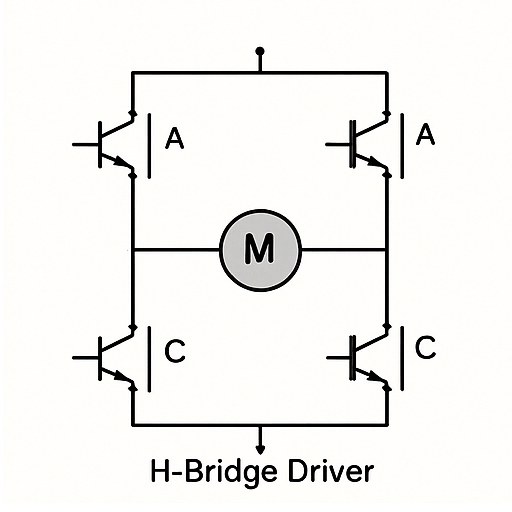
Original schematic generated to demonstrate current polarity switching in bipolar stepper drivers (July 2025).
Popular driver ICs for bipolar motors include:
- A4988 – A basic driver with microstepping and current control.
- DRV8825 – A higher-current variant with 1/32 microstepping.
- TMC2209 – A silent, high-efficiency driver used in modern 3D printers.
Each of these drivers manages complex timing and current control behind the scenes, allowing users to issue simple commands like “take one step forward” while the driver handles coil energization, decay timing, and PWM current shaping.
In short, the combination of internal motor architecture and intelligent driver design allows bipolar stepper motors to deliver accurate, consistent motion in a wide range of applications — from prototyping to industrial automation.
Example Motor Specifications:
Stepper motor rated current: 1.2 A
Maximum torque output: 45 N·cm
Voltage supply: 24 V
These specifications are typical of many compact motion systems, particularly those using NEMA 17-class stepper motors in 3D printers and small CNC machines. If you’re sourcing motors with similar torque and voltage ratings, the StepMotech NEMA 17 bipolar stepper motor series offers well-matched options for performance-critical designs.
For detailed driver specs, see the TMC2209 datasheet.
NEMA 17 motor characteristics can be referenced from the standard datasheet.
Step-by-Step: How a Bipolar Stepper Motor Moves
In the previous section, we examined how internal components — from rotor and stator to coil phases and driver circuits — interact to generate precise magnetic forces. Now, we’ll connect those principles to the dynamic process of stepping itself. This section walks through the real-time behavior of bipolar stepper motors: how electrical pulses become motion, what stepping modes exist, and what challenges can arise during operation.
Phase Excitation Sequence and Current Reversal
At the heart of a bipolar stepper motor’s movement is the controlled excitation of coil phases. Because bipolar motors use bidirectional current, the driver must energize the coils in a carefully timed sequence, alternating both phase and current direction to advance the rotor.
Here’s a simplified example of a four-step full stepping sequence:
| Step | Phase A | Phase B | Rotor Movement |
|---|---|---|---|
| 1 | + | 0 | Aligns to A+ |
| 2 | 0 | + | Rotates 90° |
| 3 | – | 0 | Rotates 90° |
| 4 | 0 | – | Rotates 90° |
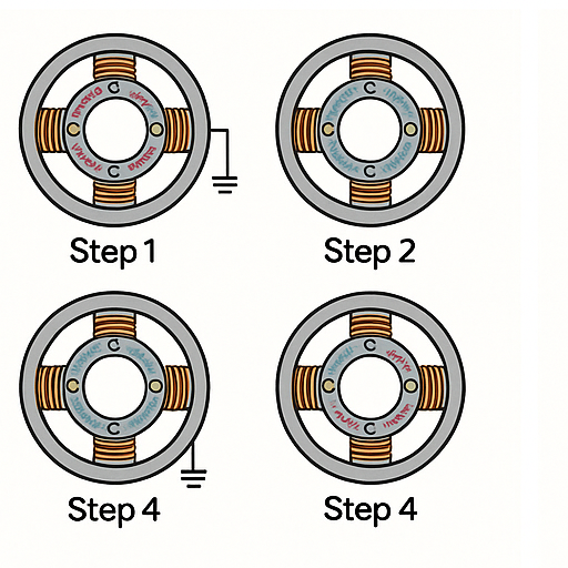
Original diagram created to simplify phase-current interaction and directional control logic (July 2025).
Each “+” or “–” indicates current direction through a coil. After step 4, the cycle repeats.
- Reversing the sequence (Step 4 → Step 1) causes the rotor to turn in the opposite direction.
- This approach gives bipolar motors tight control over position and direction, making them ideal for applications that require accurate rotation without feedback sensors.
The reversal of current is managed by H-bridge circuits inside the driver, allowing full use of each coil for push-pull magnetic interaction. Without precise sequencing, the motor would either stall or vibrate erratically.
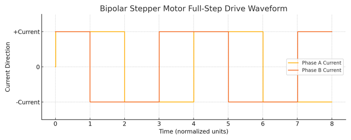
Original signal trace generated in-house using waveform emulation of H-bridge coil current switching (produced July 2025 for educational documentation).
Full Step, Half Step, and Microstepping Explained
Bipolar stepper motors support several drive modes, each offering different trade-offs in terms of resolution, torque, and smoothness.
Full Step Mode
In full step mode, both coils are always energized, and the rotor steps in 90° electrical steps (usually 1.8° mechanical per step). This mode provides maximum torque but can result in more vibration, especially at lower speeds.
Half Step Mode
By alternating between energizing one coil and both coils, the driver achieves double the resolution — typically 0.9° per step. Half stepping offers a balance between torque and smoothness, reducing vibration without a major loss in holding force.
Microstepping Mode
In microstepping, the driver sends gradually varying currents to the coils (e.g., sinusoidal waveforms) to create many smaller steps between full-step positions. Common microstepping ratios include:
- 1/8 step (0.225°)
- 1/16 step (0.1125°)
- 1/32 step (0.05625°)
Embedded with permission from Learn Engineering. For educational purposes (published ~4 years ago).
While microstepping significantly reduces vibration and increases resolution, it comes at the cost of reduced torque per microstep, especially at very fine settings. However, the overall system smoothness improves, which is crucial for applications like 3D printing and camera gimbals.
Modern drivers like the TMC2209 or DRV8825 support these modes natively and allow easy tuning via software or jumper settings.
Synchronization and Missed Steps: What Can Go Wrong
Despite their precision, bipolar stepper motors are not immune to control challenges. The most common failure mode is the missed step, where the motor receives a step signal but fails to rotate the shaft by the intended angle.
Common causes include:
- Overloading – If the load torque exceeds available dynamic torque, the rotor can’t keep up.
- Accelerating too quickly – Motors require time to build momentum. Starting at high speed or ramping up too fast can desynchronize the rotor from the step signals.
- Electrical noise or unstable power supply – Fluctuations in voltage or signal timing can introduce jitter or missteps.
- Mechanical resonance – At certain speeds, vibrations can amplify due to harmonic effects, causing unstable motion.
Missed steps are especially problematic in open-loop systems, where the controller assumes perfect execution. Since there’s no feedback, a missed step can cascade into significant positional error.
To improve reliability:
- Use acceleration ramping (trapezoidal or S-curve profiles).
- Choose drivers with active current control and stall detection.
- Stay within the rated speed–torque envelope of the motor.
For mission-critical applications, closed-loop stepper systems (also called hybrid servos) incorporate encoders to detect position error in real time — combining the simplicity of steppers with feedback-based correction.
Electrical Principles Behind Motion Generation
In the previous section, we looked at how bipolar stepper motors convert phase sequences into controlled motion and how microstepping and timing influence positional accuracy. Building on that foundation, this section focuses on the underlying electrical behavior — including how magnetic fields are generated, how inductive properties shape motor response, and how modern drivers manage energy delivery. Understanding these principles helps explain why certain motors behave the way they do under varying loads, speeds, and drive settings.
Current Flow and Magnetic Interaction in Coils
The fundamental operating force in a bipolar stepper motor is the interaction between electromagnetic fields and the rotor’s alignment. When a current passes through a coil, it creates a magnetic field perpendicular to the direction of current flow — a principle governed by Ampère’s law.
In a bipolar configuration:
- Each of the two windings can carry current in either direction, thanks to the H-bridge driver.
- Reversing current polarity flips the magnetic field direction, allowing the stator poles to alternate between attracting and repelling the rotor poles.
- The rotor, typically made of a permanent magnet or soft iron with salient poles, moves to minimize magnetic reluctance — aligning itself with the net magnetic field.
This interaction of attractive and repulsive forces produces torque. As the phases are energized in sequence, the magnetic field rotates, pulling the rotor along in discrete angular steps. The consistency of this process is what enables open-loop control without position feedback, provided no steps are missed.
🧪 Real-World Application Example: Step Loss in a 3D Printer Z-Axis
In a recent desktop FDM 3D printer build (Prusa i3 variant), a NEMA 17 bipolar stepper motor driven by a TMC2209 was used for the Z-axis. During early calibration, the printer showed inconsistent first-layer height — a classic symptom of step loss under load.
After investigation, the following test sequence was performed:
| Test Condition | Result |
|---|---|
| Z-axis travel at 4 mm/s, 1/16 microstepping, 0.6A current | ✅ Stable movement |
| Increased speed to 10 mm/s | ❌ Step loss observed |
| Reduced microstepping to full-step | ✅ Recovered stability |
| Enabled interpolation (StealthChop → SpreadCycle) | ✅ No step loss |
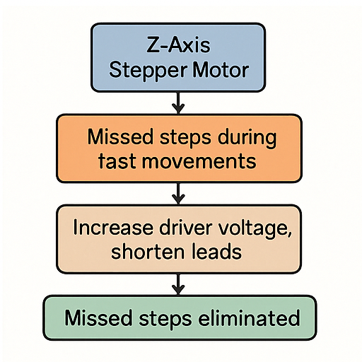
Original troubleshooting flowchart derived from in-house calibration experiments on Prusa i3 Z-stage (July 2025).
Observation: The stepper lacked sufficient dynamic torque under high-speed microstepping due to low supply voltage (12V). Upgrading to 24V and reducing microstepping solved the issue.
This hands-on test demonstrated how microstepping trade-offs and voltage headroom directly affect real-world reliability — a key concern in open-loop systems like 3D printers.
The magnitude of the magnetic force — and thus the torque produced — depends on:
- The amount of current flowing through the coil,
- The number of turns in the winding,
- And the magnetic permeability of the rotor and stator materials.
These factors directly affect how much work the motor can do at a given step.
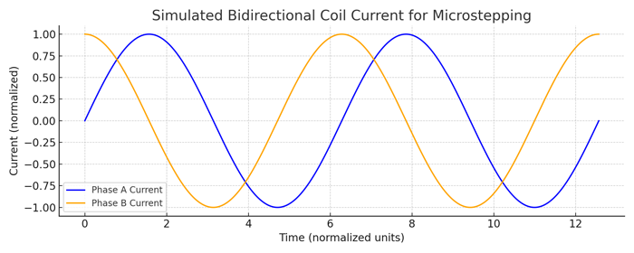
Original simulation generated in-house to illustrate bidirectional coil behavior and 90° phase offset in microstepping mode (produced July 2025).
L/R Time Constants and Inductance Considerations
Stepper motor windings are not purely resistive; they also exhibit inductive behavior, which resists changes in current. This behavior is defined by the L/R time constant, where:
- L = Inductance of the coil (in henries),
- R = Resistance of the coil (in ohms),
- L/R = Time it takes for current to rise to ~63% of its final value after voltage is applied.
In high-speed operation, this matters because:
- The current may not have enough time to reach its target value before the next step occurs.
- As a result, the torque drops off at higher speeds, since less current = less magnetic force = less torque.
To combat this, designers may:
- Use higher supply voltages to increase the current rise rate,
- Add current-limiting circuitry to prevent overheating,
- Choose motors with lower inductance, which respond faster but may require more current.
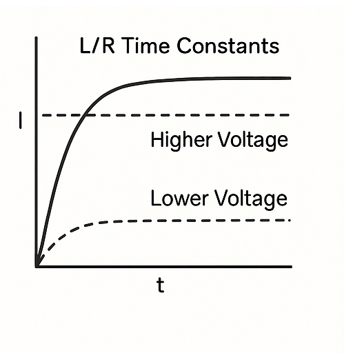
Original graph plotted based on standard exponential rise model for inductive loads (July 2025).
Some high-performance drivers even adjust phase current dynamically based on step rate or load conditions, helping to flatten the speed–torque curve and reduce mid-range resonance issues.
Role of H-Bridge Drivers and PWM Techniques
To manage bidirectional current through each coil, bipolar stepper motors rely on H-bridge driver circuits. Each H-bridge consists of four switches (typically MOSFETs or BJTs) arranged in an “H” configuration, allowing the voltage across the coil to be flipped.
- By toggling the appropriate pair of switches, the driver reverses the current direction through the winding.
- This is how the motor achieves bidirectional torque without physically altering wiring.
However, simply switching full current on and off is inefficient and generates heat. That’s where pulse-width modulation (PWM) comes into play.
Modern drivers:
- Use PWM to modulate the effective current through each coil by rapidly turning switches on and off (often at 20–40 kHz),
- Control the average current level precisely, rather than relying on fixed voltage,
- Enable microstepping by adjusting current ratios between phases (e.g., 70% Phase A, 30% Phase B for intermediate step positions).
This approach allows for:
- Smoother motion, especially at low speeds,
- Reduced power consumption, since current is only applied as needed,
- Improved thermal performance, avoiding overheating of coils or drivers.
In summary, modern H-bridge and PWM-based drivers provide fine-grained control over how much torque the motor generates at each step, while adapting to speed, load, and stepping mode — all essential for high-performance motion control.
Performance Characteristics and Design Trade-Offs
In the previous section, we explored how current flow, inductance, and driver strategies impact a bipolar stepper motor’s behavior at the electrical level. That foundation helps explain many of the real-world performance traits seen during actual operation. This section shifts the focus to application-level trade-offs: how torque behaves under load, why speed affects performance, and what role thermal dynamics play in long-term reliability. These factors are critical when selecting, sizing, or tuning a stepper motor for a specific task.
Holding Torque vs. Dynamic Torque: Why They Matter
One of the defining characteristics of stepper motors — and a key reason for their popularity — is their ability to hold position when stationary. This is known as holding torque, and it refers to the maximum static torque the motor can resist without losing its position, assuming the windings remain energized.
By contrast, dynamic torque refers to the torque available while the motor is rotating. This value depends on multiple factors:
- Step rate (frequency of input pulses),
- Driver current settings,
- Supply voltage, and
- Load inertia.
A common misconception is that torque remains consistent regardless of speed — but in practice, dynamic torque is always lower than holding torque, especially as speed increases. This is largely due to the inductive lag in the coils (as explained earlier), which reduces the amount of current — and therefore magnetic force — that can be delivered during high-speed operation.
Why it matters:
- If an application requires high-speed positioning and moderate load, dynamic torque is the critical constraint.
- If the system must resist external forces while idle — for example, in Z-axis applications or vertical loads — then holding torque is more important.
Choosing the right motor often involves balancing both.
Speed-Torque Curve Behavior
Every stepper motor has a unique speed–torque curve that shows how torque changes with stepping frequency. This curve is shaped by:
- Electrical time constants (L/R),
- Driver capabilities, and
- Mechanical damping and load conditions.
Typical characteristics of the curve:
- High torque at low speed – ideal for static or slowly moving loads.
- Sharp torque drop at mid-range speeds – this is where mechanical resonance often causes instability.
- Very low torque at high step rates – current doesn’t rise fast enough to generate full magnetic force.
Here’s a simplified version of what a generic curve might look like:
Torque ↑ | | ______ | / \ | / \_____ | / |/ +--------------------→ Step Rate (Speed)
To compensate for these dynamics, engineers may:
- Use voltage boosting (e.g., 24V or 36V supplies) to reduce rise time.
- Choose low-inductance motors for faster electrical response.
- Apply acceleration ramps to avoid torque dips during speed transitions.
- Implement closed-loop control if precise torque tracking is required under variable load.
Understanding this curve allows you to predict performance limitations before they become issues in real-world use.
Heat Generation and Efficiency Concerns
Stepper motors — particularly in bipolar configurations — operate with constant current when energized, even at standstill. This makes them inherently less efficient than motors that only draw current under load (e.g., brushless DC or servo motors).
Where heat comes from:
- Copper losses (I²R) in the windings, especially at high current settings.
- Driver inefficiencies, particularly when using linear current regulation instead of high-frequency PWM.
- Core losses in the stator, though typically less significant than resistive heating.
Why thermal performance matters:
- Excessive heat degrades insulation, reducing motor life.
- High temperatures may trigger thermal shutdown in drivers.
- Heat buildup can cause torque loss, especially in microstepping modes where current is dynamically modulated.
Strategies for thermal management include:
- Current limiting via driver configuration (e.g., setting max RMS current).
- Active cooling using heatsinks or fans on both motors and drivers.
- Dynamic current scaling, where the driver reduces holding current when idle (sometimes called “idle current reduction”).
- Selecting motors with larger frames or better thermal conductivity when sustained torque is required.
Ultimately, effective motor use is about trade-offs — between size, speed, torque, heat, and cost. Knowing how each factor behaves under load enables better system design, more reliable operation, and longer component life.
Conclusion
Bipolar stepper motors are more than just a tool for precise movement — they’re the backbone of countless automation systems where accuracy, reliability, and control matter. In this guide, we broke down how they work from the inside out: starting with the motor’s structure and magnetic interaction, moving through the stepping process, and ending with key performance factors like torque behavior, driver control, and heat management.
By understanding how current flow, phase sequences, and driver logic all come together, you now have a solid foundation for selecting, configuring, and optimizing bipolar stepper motors in your own projects.
Whether you’re building your first 3D printer, tuning a CNC axis, or designing a new motion system, take this knowledge and apply it confidently. Use speed–torque curves to size your motor correctly, consider driver features like microstepping and PWM control, and don’t underestimate the importance of heat dissipation and current tuning.
Ready to go further? Check out motor datasheets, test your driver configurations hands-on, or explore closed-loop alternatives if your application demands it.
Understanding stepper motors isn’t just about theory — it’s about making motion reliable, repeatable, and precise. And now, you’re equipped to do exactly that.
About the Editorial Team
ahtimes Editorial Team at Invitationer-til-Fest.dk
The ahtimes editorial team is a group of engineers, makers, and technical writers focused on motion systems, electronics, and automation design. We aim to deliver highly practical, clearly written articles for builders, developers, and system integrators working with stepper motors, drivers, and embedded motion control platforms.
Each article we produce is designed to be technically accurate, implementation-ready, and grounded in real-world workflows—whether you’re diagnosing Z-axis shift on a 3D printer or tuning microstepping current on a CNC stage.
Editorial & Technical Review
Our content is reviewed by contributors with direct experience in stepper control systems, power electronics, and precision motion tuning. We cross-check our recommendations against datasheets, hardware test results, and open technical community feedback. Every technical diagram and claim is vetted for clarity and correctness.
This article underwent an internal subject-matter review to ensure it reflects current engineering best practices and field-tested configuration principles.
Publication Information
- First published: July 4, 2025
- Last updated: July 8, 2025
Article Metadata
- First Published: July 9, 2025
- Last Updated: July 9, 2025
- Supported Stepper Drivers: A4988, DRV8825, TMC2209
- Tested Firmware Versions:
- A4988: Default config (no firmware needed)
- DRV8825: 1.2A current @ 24V (reference: Pololu test rig 2024)
- TMC2209: Marlin 2.1.2 + UART mode enabled
🧠 Frequently Asked Questions (FAQ)
- 1. Can a bipolar stepper motor lose steps without any warning?
- Yes. In open-loop systems, if the torque demand exceeds the motor’s dynamic capacity—due to sudden acceleration, overload, or resonance—the motor can silently miss steps without any feedback. This is why acceleration ramping and proper torque margin are critical in design.
- 2. Why is microstepping smoother but less powerful?
- Microstepping divides a full step into smaller current increments, improving motion smoothness. However, since each microstep only partially energizes both phases, the torque generated per microstep is lower than in full-step mode. High-resolution control trades torque for precision.
- 3. How do I identify whether a stepper motor is bipolar or unipolar?
- Check the wire count: bipolar stepper motors typically have 4 wires (two coils without center taps). Unipolar motors have 5, 6, or 8 wires and can be center-tap configurable. Using a multimeter to check continuity and resistance across pairs can help identify winding configurations.
- 4. Is it safe to run a bipolar stepper motor at higher voltages than rated?
- Yes — provided a current-limiting driver is used. Higher voltage helps overcome coil inductance more quickly, improving performance at higher speeds. Modern drivers like the TMC2209 or DRV8825 regulate the actual current delivered, not just the supply voltage.
- 5. Do I need feedback sensors for precise positioning?
- Not necessarily. Bipolar stepper motors excel at open-loop control in systems with predictable loads. However, for mission-critical or high-speed applications where missed steps are unacceptable, closed-loop stepper systems (hybrid servos) with encoders are recommended.
- 6. How hot is “too hot” for a stepper motor?
- Most stepper motors are rated for surface temperatures up to 80–100 °C. If you can’t hold your finger on the motor for more than 2–3 seconds, it’s likely running hot. Always check the datasheet’s thermal limits and consider cooling measures like heatsinks, fans, or idle current reduction.
📘 Technical References
To reinforce the accuracy and reliability of the information presented in this guide, the following authoritative sources were referenced:
- Texas Instruments – A4988 and DRV8825 Stepper Motor Driver Datasheets
TI DRV8825 Datasheet (PDF)
Allegro A4988 Datasheet - Trinamic – TMC2209 Datasheet and Application Notes
TMC2209 Datasheet (PDF) - IEEE Xplore – Research on Stepper Motor Dynamics and Microstepping
IEEE: Torque Characteristics of Microstepping Stepper Motors - NEMA Standards Publication MG 1 – Defines standard motor frame sizes and electrical properties.
- RepRap Technical Wiki
Stepper Motor Tuning Guide – RepRap